Connector types
A connector type describes the shape of a physical connector — its pin pitch, body size, number of rows, and where the pin lines exit — independent of any board. Board connectors reference a type by name through their type field.
Type definitions live in the package's src/pinconnect/connectors/ folder, one .toml file per type. The filename is the type name: XH-F.toml defines the XH-F type. When pinconnect runs, it first checks the board's connector_dir (defaults to ./connectors next to the board config), then falls back to the built-in types bundled with the package.
Built-in types
The table follows the designer's Type menu, which lists each type under a category by a plainer name. Type is what a board's type field holds; the menu entry is only what the designer shows for it.
| Type | Designer menu | Style | Notes |
|---|---|---|---|
PH-F |
JST › PH (2.0mm) | latch | JST PH female, single row |
XH-F |
JST › XH (2.5mm) | latch | JST XH female, single row |
MX-F-2R |
Molex › Micro-Fit 3.0 Dual Row | grid | Micro-Fit female, two rows |
MX-F-1R |
Molex › Micro-Fit 3.0 Single Row | grid | Micro-Fit female, single row |
SHERLOCK-F |
Molex › Sherlock (2.0mm) | sherlock | Sherlock female, single row; body widens at 3 ways or fewer matching real Sherlock connectors |
HDR-127-2R |
Pin Header › 1.27mm Dual Row | header-male | 1.27 mm male pin header, two rows |
HDR-127 |
Pin Header › 1.27mm Single Row | header-male | 1.27 mm male pin header |
HDR-200-2R |
Pin Header › 2.00mm Dual Row | header-male | 2.00 mm male pin header, two rows |
HDR-200 |
Pin Header › 2.00mm Single Row | header-male | 2.00 mm male pin header |
HDR-254-2R |
Pin Header › 2.54mm Dual Row | header-male | 2.54 mm male pin header, two rows |
HDR-254 |
Pin Header › 2.54mm Single Row | header-male | 2.54 mm male pin header |
ST-254 |
Screw Terminal › 2.54mm | screw-terminal | 2.54 mm pitch screw terminal |
ST-508 |
Screw Terminal › 5.08mm | screw-terminal | 5.08 mm pitch screw terminal |
ST-BR-508 |
Screw Terminal › 5.08mm Barrier | barrier | 5.08 mm barrier screw terminal strip |
ST-BR-950 |
Screw Terminal › 9.5mm Barrier | barrier | 9.5 mm barrier screw terminal strip |
none |
Other › None (marker only) | none | Nothing at all; marks a spot on the board that has no pinout to show |
button |
Other › Push Button | button | Tactile push-button / switch footprint |
slide-switch |
Other › Slide Switch | slide-switch | Slide switch; its pins are the slider's positions |
STEPSTICK-F |
Other › StepStick Socket | stepstick | StepStick stepper-driver socket, female: two 8-way 2.54 mm headers and a two-pin tower, 18 pins in all |
USB-C |
Other › USB-C | box | Simple rectangular body |
XT30-2+2 |
Other › XT30 (2+2) | xt30 | XT30 power + 2 signal pins |
Male and Female refer to the gender of the plastic housing of the connector, not the pins, as that's what the end user will see when using the board.
USB-C and button "connector types" are meant to be used to highlight the locations of these on your board, not for their pinouts. To render properly, they shouldn't include pins in your board TOML. slide-switch also highlights a location rather than a pinout, but it uses pins. Pins mark slider positions, rendered without pin circles.
The header-male types are also the ones that take jumper settings: where a header's jumpers go and what each position means, drawn as jumper caps over the pins. A board connector of any other type with settings is an error.
none goes further and draws nothing at all: a connector of that type is only a hotspot over the image, carrying a name and an optional description. Use it to point at anything with no pinout to show, such as a microcontroller, a mounting hole, or a fuse holder. It ignores any pins you give it, and both its list entry and its tooltip leave out the type name and pin count that other connectors carry, so nothing reads as "0-pin".
Each type rendered, so you can pick one by its look:
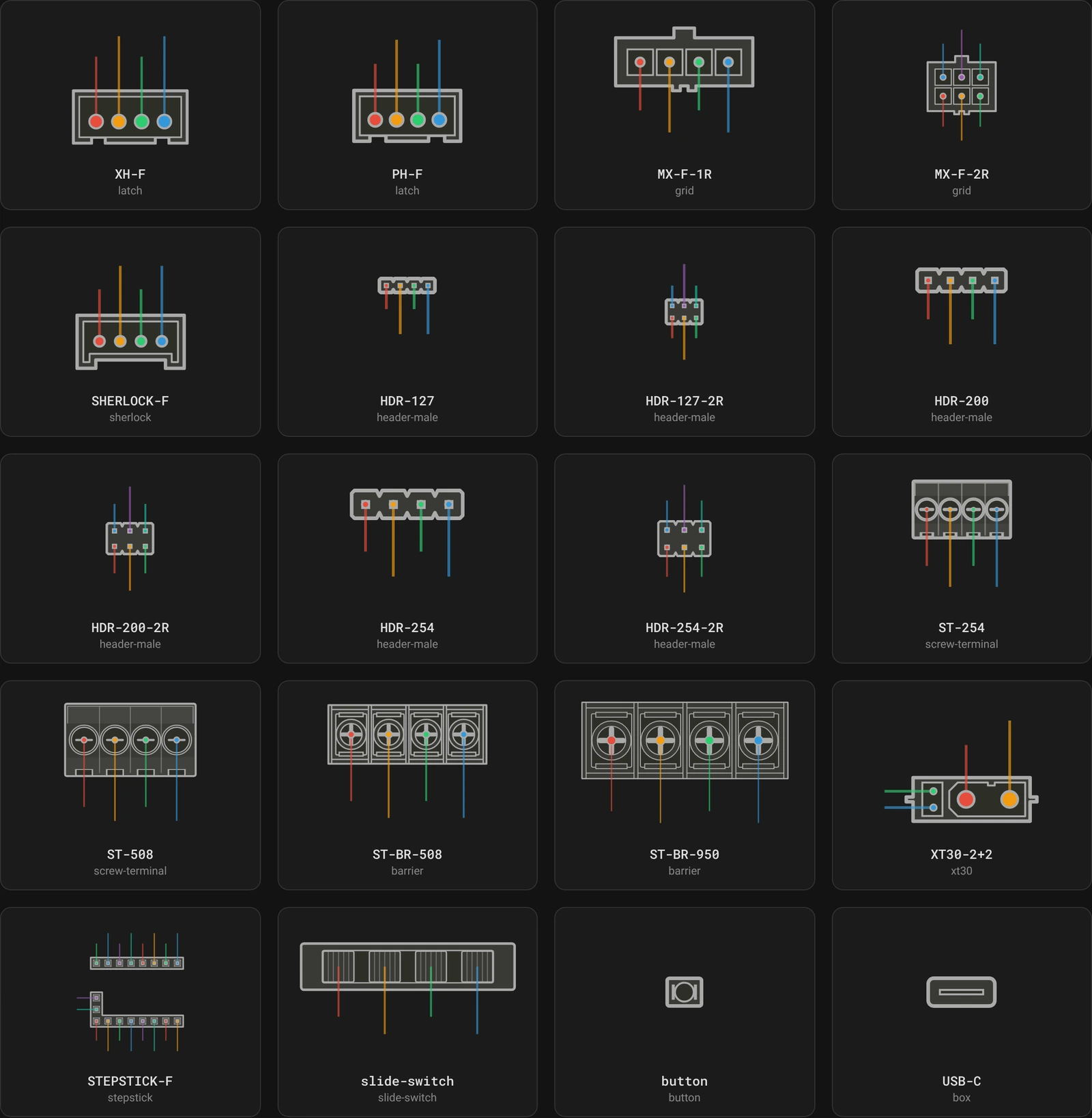
none is missing from that gallery on purpose, since it has nothing to draw. The live connector gallery shows the same cards as a pinout: hover one to see the type with sample pin labels.
Anatomy of a type file
A type file has a [connector] table and a [geometry] table:
[connector]
name = "Micro-Fit"
category = "Molex"
menu_name = "Micro-Fit 3.0 Dual Row"
style = "grid"

[geometry]
pin_pitch = 12.0
height = 37.6
wall = 2.5
pin_cy = 25.9
pin_radius = 1.8
pinout_side = "bottom"
line_length = 8.0
rows = 2
row2_pin_cy = 13.7
row2_pinout_side = "top"
row2_line_length = 8.0
cavity_size = 10.5
That is MX-F-2R.toml verbatim. Copying a bundled type that resembles what you are drawing is the fastest way to start a new one.
[connector]
name— human-readable name for the connector family, shown on the generated page beside each connector's pin count, as inMicro-Fit · 4-pin.category— optional. The group the designer's Type menu lists the type under, such as"Pin Header". Groups are in alphabetical order withOtherlast, and a type without a category goes inOther.menu_name— optional. The type's entry in that group, such as"2.54mm Dual Row"; without it the menu showsname. Entries are in alphabetical order within their group, with numbers compared by value, so9.5mmcomes before10mm. The designer's connector list shows it too. Neithercategorynormenu_namechanges anything else: a board still names the type by its filename, and the generated page showsname. A value that is not a string is rejected.default_pins— optional list of the pins a new connector of this type starts with, written like a board's pins:{ name = "GND", color = "#2C3E50", row = 1 }, withcolorandrowoptional. It is what the designer's New Connector creates, in list order. Without it a new connector starts with one pin namedPIN1. It does not change whatpinconnectdraws, but the loader checks it on every run, so a malformeddefault_pinsin a board's own connector type stops the command with an error. Onlyname,colorandroware allowed; any other key, acolorthat is not a string, or arowbeyondrowsis rejected.style— how the body is drawn. One of:box— a plain rectangle.latch— a latching housing (JST XH / PH look).grid— a gridded housing with cavities (Micro-Fit look); usescavity_size.xt30— the XT30 power-connector body.header-male— a pitch-scaled male pin-header housing with square cavities and keyed joints.screw-terminal— a screw-terminal with circular screw heads and side wire-entry slots.barrier— a barrier screw-terminal with individual metal cages and cross-drive screws.button— a tactile push-button / switch footprint (a round actuator between two pads).slide-switch— a slide switch: a recessed actuator track carrying a knurled slider block at each of its labeled positions; usescavity_sizefor the slider.stepstick— a StepStick socket: two 8-way female headers drawn as plain rectangles with a square socket, funneled at the entry, per way, and a two-pin tower standing on the lower header. The tower is drawn only when the connector has pins on row 3, so a plain A4988 or DRV8825 socket shows none. Where it stands, and so which way round the connector goes, followsrow3_padding_left. Usesrows = 3, therow3_*keys, andcavity_sizefor the socket's mouth. The tower has to fit between the two headers, which the loader checks.sherlock— a Sherlock housing: two latch ears on the body edge, and a stepped, chamfered mating half on the narrow sizes; usesflare_max_pins/flare_width.none— nothing is drawn. The connector becomes a plain marker on the board; see the note above.
[geometry]
The geometry fields position the pins and the lines that run from each pin to its label. Any field you omit falls back to the default below, so a minimal type only needs to specify what differs.
Values are in the type's own drawing units, scaled to the connector's bounding box on the board — only their proportions matter. All bundled types are drawn at roughly 4 units per millimeter of the real part (XH-F's 2.5 mm pitch is pin_pitch = 10.0, ST-508's 5.08 mm is 20.0), so multiplying datasheet millimeters by 4 keeps a new type consistent with the library.
Unknown keys are rejected: a typo fails at load time with an error naming the offending key rather than being silently ignored.
Body and pins
| Key | Default | Meaning |
|---|---|---|
pin_pitch |
10.0 |
Spacing between adjacent pins. |
padding_left |
10.0 |
Body edge to the first pin's center. |
padding_right |
10.0 |
Last pin's center to the body edge. |
height |
23.0 |
Body height. |
wall |
2.6 |
Housing wall thickness. |
pin_cy |
13.5 |
Pin center offset from the top edge, at 0°. |
pin_radius |
3.0 |
Pin marker radius. |
pinout_side |
"bottom" |
Which side the pin lines exit: top, bottom, left, or right. |
line_length |
20.0 |
How far the pin lines extend to reach their labels. |
The pin count comes from the board config, not the type — pin_pitch and the two paddings size the body to fit however many pins the board declares.
Second row
| Key | Default | Meaning |
|---|---|---|
rows |
1 |
1, 2 or 3. The row2_* keys apply from 2 up, the row3_* keys only at 3. |
row2_pin_cy |
0.0 |
Second row's pin center offset from the top edge. |
row2_pinout_side |
"top" |
Which side the second row's lines exit. |
row2_line_length |
20.0 |
Line length for the second row. |
row2_padding_left |
-1.0 |
Second row's left padding. Negative means inherit padding_left. |
row2_pin_radius |
-1.0 |
Second row's pin radius. Negative means inherit pin_radius. |
row2_pin_pitch_y |
0.0 |
Above 0, the second row becomes a vertical column of pins spaced this far apart, instead of a horizontal row. This is how XT30-2+2 puts its two signal pins beside the power pair. |
Third row
With rows = 3 a type gets a third group of pins, always a vertical column, like the vertical form of the second row. This is how STEPSTICK-F places the two pins of its tower beside the two headers. Pins reach it with row = 3; on a type with fewer rows they fall back to row 1.
| Key | Default | Meaning |
|---|---|---|
row3_padding_left |
-1.0 |
Body edge to the column's pins. The column always stands over the body: a value past either end snaps to the nearest end pin position. Negative puts it on the last pin position of the body. STEPSTICK-F sets it to its first pin so the tower stands on the left. |
row3_pin_cy |
0.0 |
The first (top) pin's center offset from the top edge. |
row3_pin_pitch_y |
10.0 |
Spacing between the column's pins. |
row3_pin_radius |
-1.0 |
Third row's pin radius. Negative means inherit pin_radius. |
row3_pinout_side |
"right" |
Which side the third row's lines exit. |
row3_line_length |
20.0 |
Line length for the third row. |
Style-specific
| Key | Default | Meaning |
|---|---|---|
cavity_size |
0.0 |
Cavity size for the grid style; slider size for slide-switch; socket size for stepstick. |
mating_pin_scale |
1.0 |
Scale of the visible metal contact inside a screw-terminal wire opening. |
flare_max_pins |
0 |
Pin count at or below which the housing flares wider. 0 never flares. |
flare_width |
0.0 |
Extra body width per side while flared. |
flare_* exists for families that widen the molding below a few ways (like Sherlock). The flare widens the outer body, and the pin centers move with it so the pins stay centered.
A type is one shape per family, not one per size. Where a family changes shape rather than just width — as SHERLOCK-F does at 3 ways or fewer — the style handles that branch internally, so a board only ever names SHERLOCK-F.
Adding a new type
There are two places a type can live, depending on whether it is just for your board or belongs in the shared library.
For one board (no changes to the package). Create <TYPE>.toml in the board's connector_dir — ./connectors next to the board config unless you set otherwise — and reference it with type = "<TYPE>". That folder is searched first, so a file named after a bundled type also lets you override one locally.
A board-local type is only visible to pinconnect. The designer has your config text but not your folder, so it cannot offer the type, and if the name matches a bundled one it will quietly draw the bundled shape instead. It says so when that happens. Render those boards from the command line.
For the shared library. Create src/pinconnect/connectors/<TYPE>.toml in a clone of the PinConnect repository instead. It is then available everywhere, the designer included once you reload it, with nothing else to regenerate or restart. Give it a category and a menu_name so the designer lists it beside its relatives rather than under Other.
Either way, copy an existing type with a similar body as a starting point, and iterate by generating a test board and eyeballing the result — a connector does not have to sit on a real board image while you tune geometry.
A new style cannot be added from a config file, because each one is custom drawing code. You can open a feature request for new designs, or write your own in renderer.py and open a pull request. There is one renderer, so a style is written once and the designer picks it up automatically.
The designer and the generator cannot drift
Nothing needs regenerating after you add or edit a type. The designer loads the pinconnect package into the browser and reads these TOML files through it, so the bundled library is the single source of truth for both.
This was not always so: the designer used to carry a hand-written copy of the drawing code and JSON copies of every type, which had to be kept in step by hand. Both are gone.