The designer
The designer is where a board photo becomes a pinout. You load an image, draw a box over each connector, label the pins, and press Generate. It also writes a board config as you work, which you save so you can come back to the board later.
It runs the real generator in your browser rather than an imitation of it, so the preview is the file you download, and that file is identical to what the pinconnect command produces from the same config.
Running it
Use the hosted designer at https://pinconnect.isiks.tech. Nothing is uploaded: your photo and your config stay in the browser.
To run it yourself, install the tool and run it with no arguments:
That picks a free port, opens a browser, and prints the address. Add --port 8000 to choose the port, or --no-browser to leave the browser alone.
The designer must be served over HTTP. It fetches its runtime at startup, so opening index.html from disk does not work. To serve it with your own web server, see serving the designer by hand.
The interface
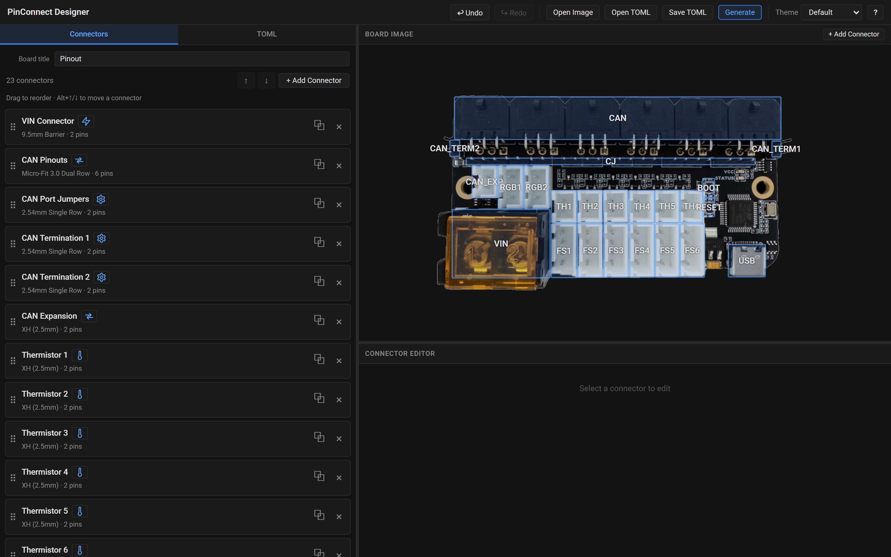
A toolbar across the top, and three panels whose dividers you can drag:
- Toolbar: Undo, Redo, Open Image, Open TOML, Save TOML, Generate, a Theme selector, and ? for the About box.
- Connectors / TOML (left): the Connectors tab has a Board title field, which sets the generated page's title in the browser tab, above the list of the board's connectors. It is selected on your first visit. The TOML tab holds the live, editable config. The designer remembers which tab you last used.
- Board Image (top right): your photo with connector boxes over it, and the + Add Connector button.
- Connector Editor (bottom right): fields and pin list for the selected connector, and its jumper settings on a pin header. It takes all the room below the divider, and the connector drawing in it grows with it, so dragging the divider up gives a bigger drawing to work on.
While the runtime is still starting, the toolbar shows its progress and Generate and + Add Connector are disabled. Loading a photo works straight away.
The Theme selector sets the board's theme, which controls the colors, fonts and layout of the generated page, including the housing, cavity, outline and label colors of the connector drawings. The connector shapes do not change. The designer's own chrome keeps its fixed dark colors whichever theme you pick; to see a theme, use Generate. See Themes.
Workflow
1. Load a board image
Click Open Image and choose your photo, taken top-down. It sets the coordinate space for everything you place on it.
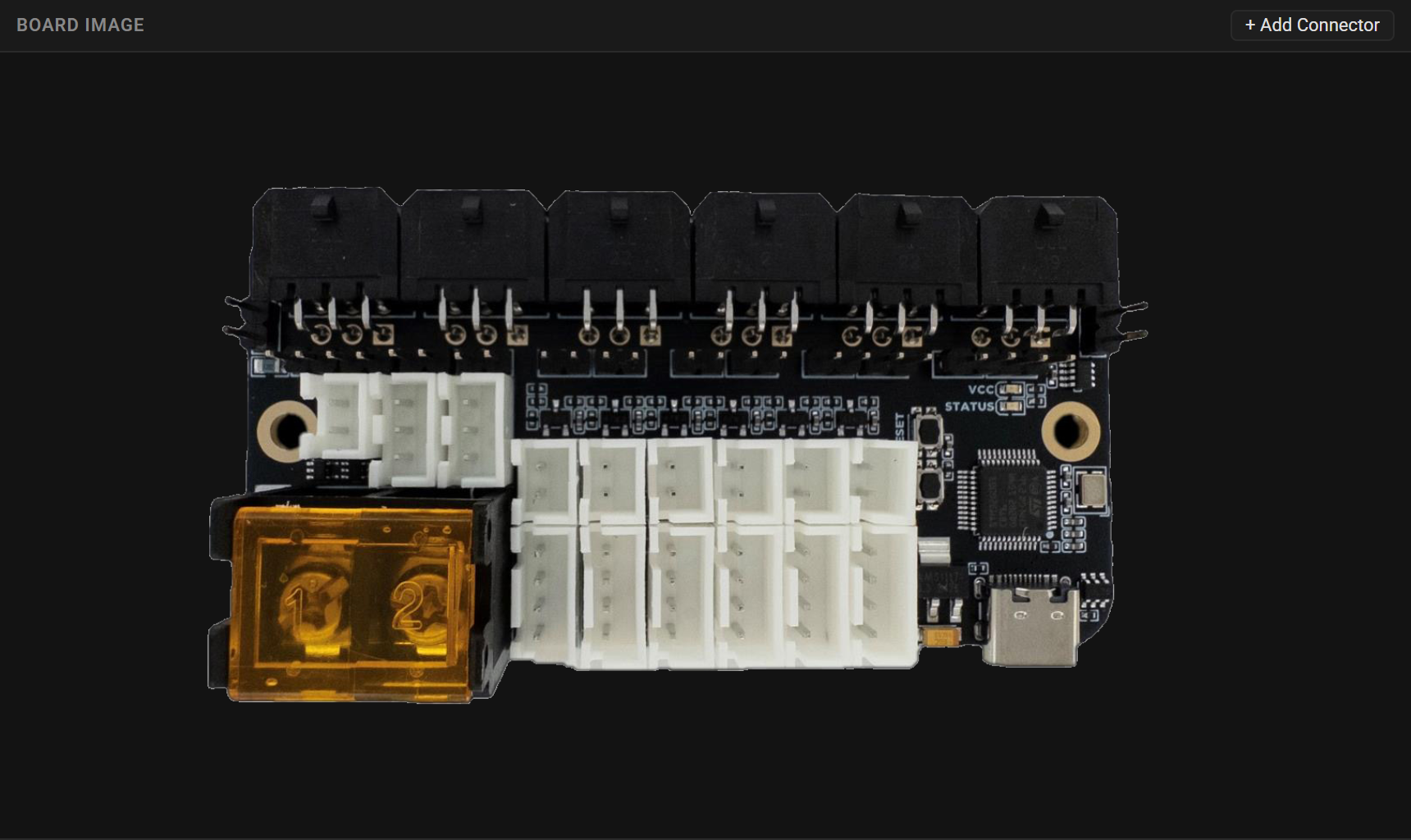
2. Add connectors
Click + Add Connector in the connector list or board panel (it becomes Cancel Draw), then drag a box over a connector. Releasing the drag opens the New Connector dialog, where you set the ID (one is suggested; it must be unique and non-empty), an optional Name (defaults to the ID), and the Type, from the same grouped menu as the connector editor's. Click Create to place it, or Cancel to discard the box. Very small boxes are ignored, so drag a real rectangle rather than clicking.
Draw mode switches off after each connector, so click + Add Connector again for the next.
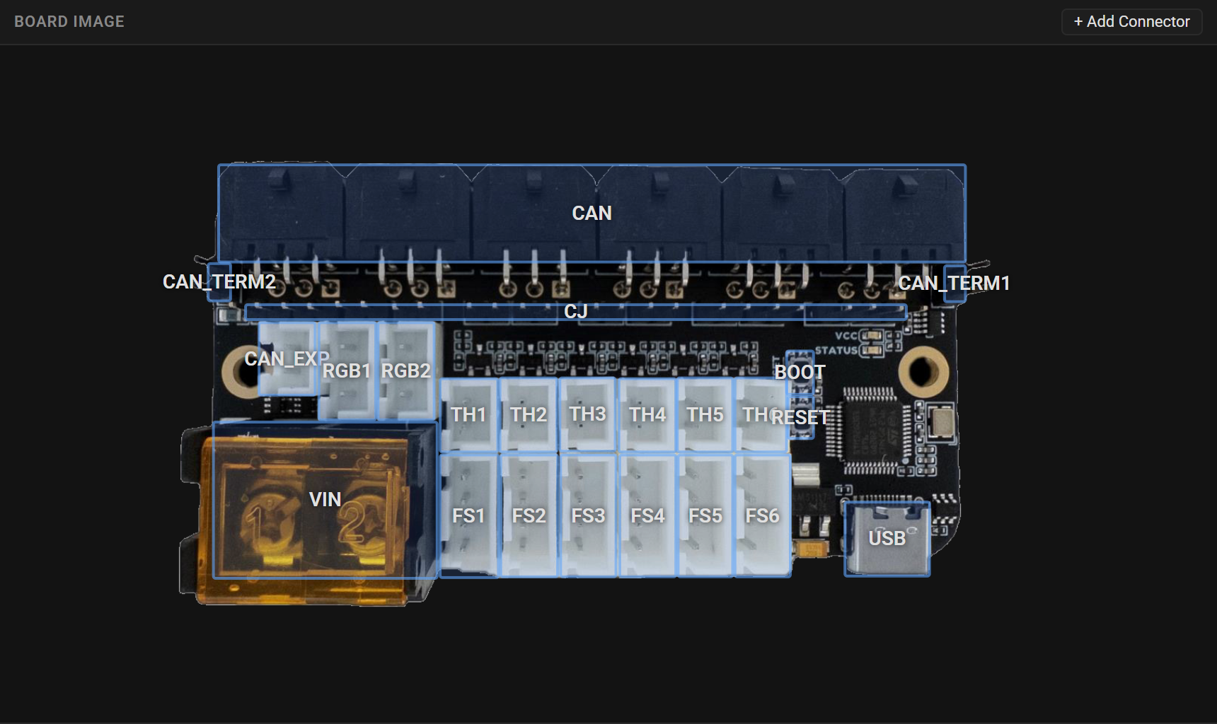
The Connectors tab shows each connector's name, type, pin count, and symbol when set. The type is shown by its menu name, such as 2.54mm Dual Row; hover it for the type's ID and group. Click a row to select that connector on the board and in the editor. Drag its handle to reorder the list, or use Move Up and Move Down for the selected connector; this also sets connector order in the generated pinout. Each row has Duplicate and Delete buttons. A duplicate keeps the pins and settings, gets a unique ID and name, and appears slightly offset on the board so you can move it into place. Reordering, duplicating, and deleting all support Undo and Redo.
In the board panel you can:
- Select a connector by clicking its box.
- Move it by dragging.
- Resize it using the handles on a selected box.
- Delete the selected connector with the
Deletekey, which is ignored while you are typing in a text field. - Zoom with the mouse wheel, centered on the cursor, and pan by dragging with the middle or right mouse button, to line boxes up precisely.
On a phone or tablet, use a finger the same way: tap a box to select it, drag it to move it, and drag a handle to resize it; touching just outside a handle grabs it too. In draw mode, dragging anywhere on the board draws a new box; outside draw mode, swiping across empty board scrolls the page as usual. Pinch with two fingers to zoom the board, and move two fingers together to pan it.
3. Edit the connector
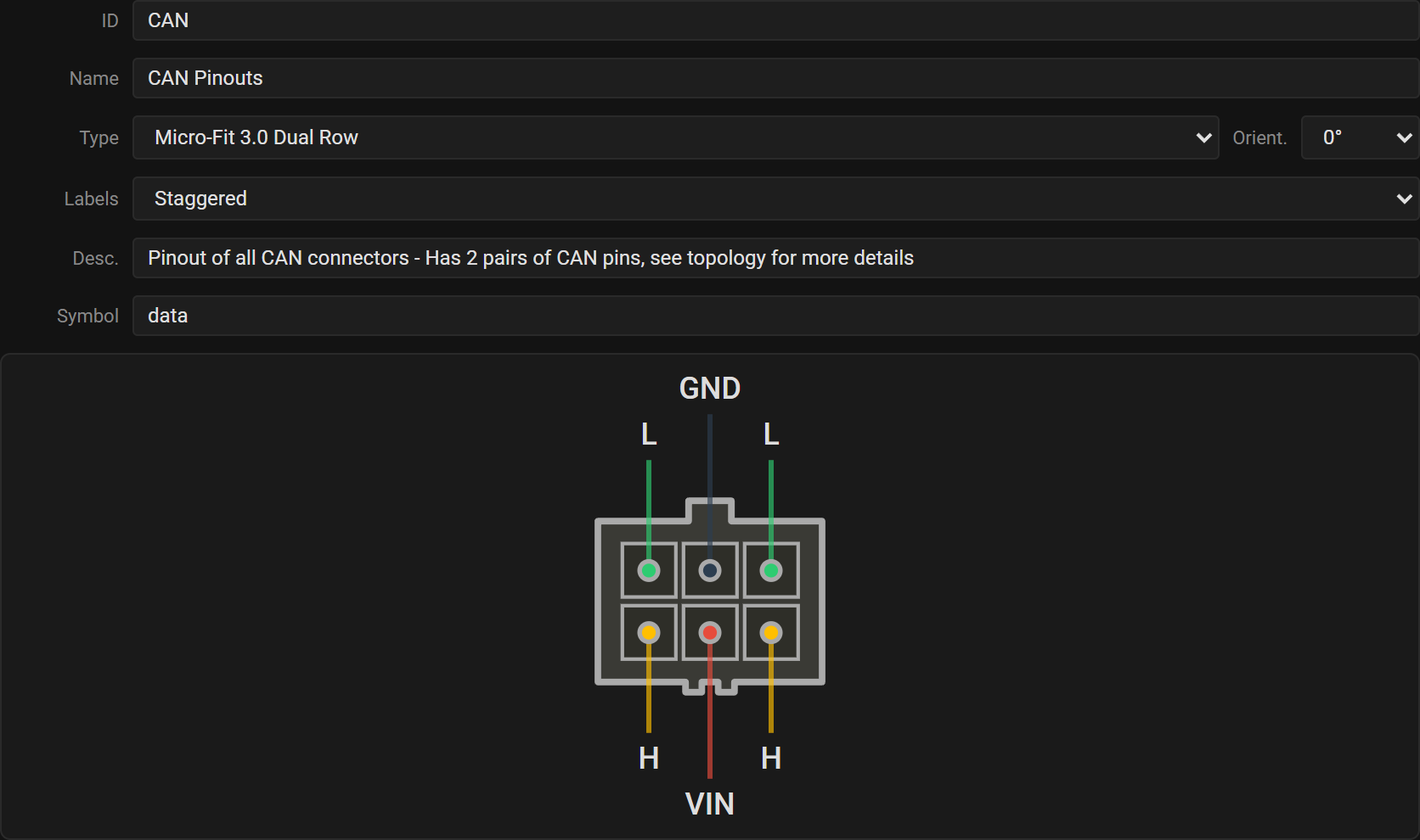
With a connector selected, the Connector Editor shows:
- ID: unique identifier.
- Name: the label shown on the diagram.
- Type: the connector type, which drives the rendered shape. The menu groups the types into JST, Molex, Pin Header, Screw Terminal and Other, and names each one plainly: the two-row 2.54 mm header is 2.54mm Dual Row under Pin Header. The config stores the type's ID, here
HDR-254-2R; the built-in types table lists both. - Orient.: rotation, one of 0°, 90°, 180° or 270°.
- Labels: flat, staircase or staggered pin labels on horizontal connectors, to avoid overlaps.
- Desc.: an optional longer description.
- Symbol: an optional icon beside the connector in the generated list and tooltip. A named icon such as
powerorfan, a literal glyph, ornone. The field suggests the built-in names as you type. Seesymbol.
The preview underneath is drawn by the generator, so it is exactly the shape the finished pinout will contain.
4. Edit the pins
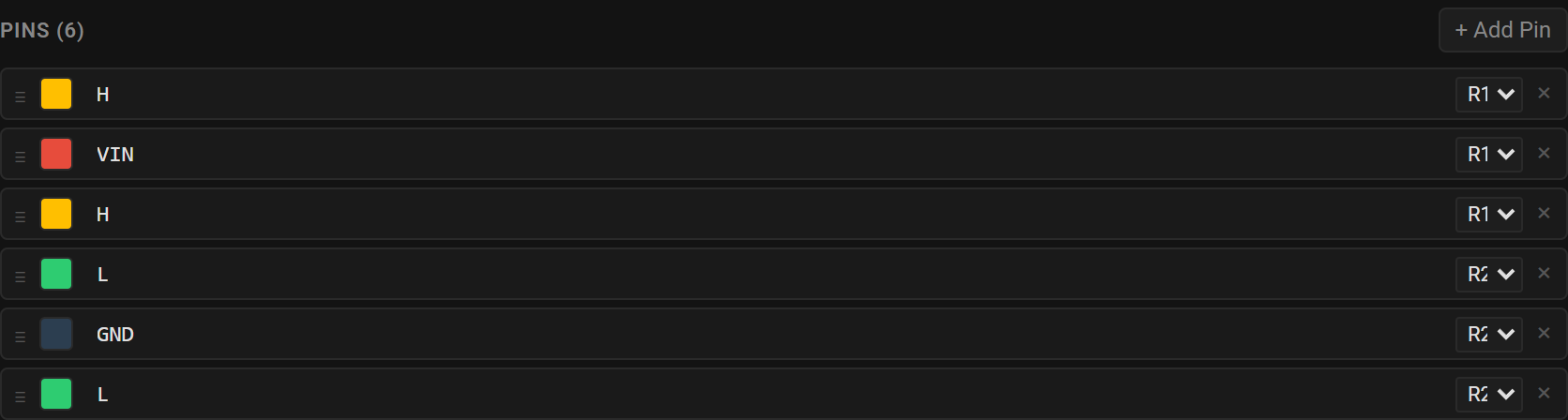
The Pins section lists the connector's pins in order:
- + Add Pin appends a pin.
- Edit each pin's name inline.
- Click the color swatch for a preset or a custom hex value.
- Set the row (R1 / R2, plus R3 on types with a third row) on multi-row connector types.
- Reorder by dragging the handle.
- Delete with the × button.
Pin order in the list is the physical pin order in the output.
5. Add jumper settings (pin headers)
A jumper header is read by position rather than by pin, so on the pin header types (the Pin Header group of the Type menu, HDR-* in the config) the editor adds a Jumper settings section below the pins, and numbers each pin in the list: those are the numbers jumpers use. Each setting is one way of fitting the header's jumpers, and becomes a button in the generated pinout. The board TOML reference shows how common headers map to settings, from an on/off jumper to a microstepping table.
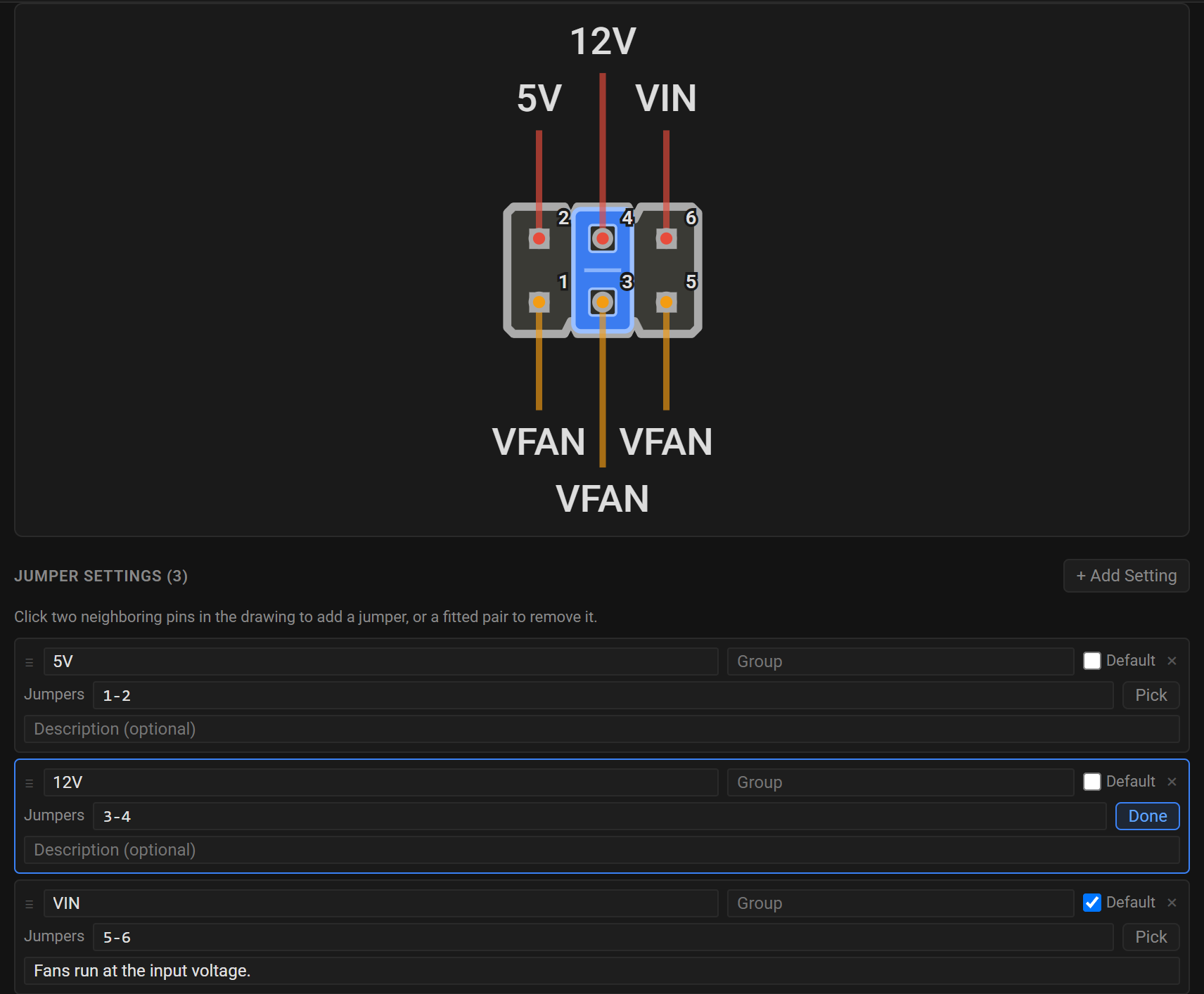
- + Add Setting appends a setting, in the same group as the last one.
- Label is the button's text, and Group makes settings into independent choices: settings with the same group are alternatives. Leave Group empty when the whole header is one choice.
- Default marks the setting the pinout opens on. Checking it clears it from the rest of the group.
- Jumpers lists the fitted jumpers as pin pairs, such as
1-2, 3-4. Leave it empty for a setting with no jumper, such as "Off". - Pick lets you build the jumpers on the drawing instead. The pins get their numbers, and clicking two neighboring pins adds the jumper between them, while clicking a pair that is already fitted removes it. A pair that is not next to each other is refused with a note. Click Done, or work in another setting, to finish.
- Description is optional text shown under the buttons while the setting is shown.
- Reorder settings by dragging their handle, or with
Alt+↑/Alt+↓from anywhere in a setting. The order is the order of the buttons. - Delete a setting with its × button.
Working in a setting shows it on the drawing, with the pins it leaves alone faded, as the generated pinout does. Deleting or moving a pin renumbers every jumper so it stays on the same pins, and a jumper on a deleted pin is removed, with a note saying which. A setting the generator would reject, such as a jumper between pins that are not neighbors, shows the generator's own message in place of the drawing. Changing a connector with settings to a type that is not a pin header keeps the settings and says why they no longer draw.
6. Edit the TOML directly (optional)
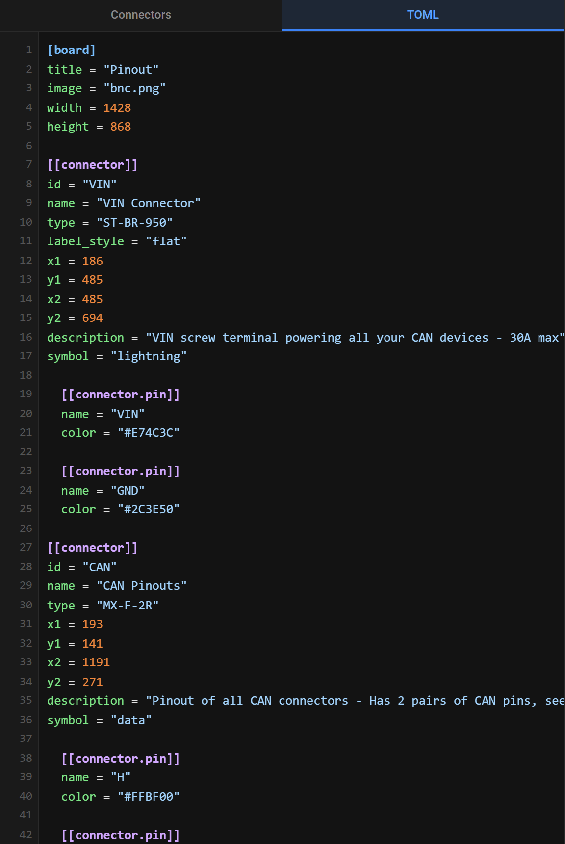
Open the TOML tab in the left panel for the fully editable TOML Source pane. The two directions stay in step: type there and the diagram updates, change something visually and the text updates. Useful for bulk edits or pasting in a config you already have. Switch back to Connectors whenever you want to browse the list.
Invalid or unfinished TOML keeps the source visible with an error and blocks visual edits until you correct it. Connector IDs must be non-empty and unique, including when you open a config or edit the source directly.
Visual edits, from picking a theme or opening an image to changing a connector, its pins or its jumper settings, rewrite only the values that change, so everything else, comments included, stays as written. Reordering and duplicating preserve each connector block's comments, formatting, and pin and setting tables. Comments between connectors travel with the following connector, and comments above a pin or a jumper setting travel with it; comments at the end of the document stay there. Put a comment inside a connector's block or inline with one of its fields if it must always travel with that connector. Deleting a connector, a pin or a setting removes the comments above it too. Duplicating copies the block and updates the copy's identity and position.
7. Generate the pinout
Click Generate. The dialog renders the pinout and shows the real page, not an approximation.
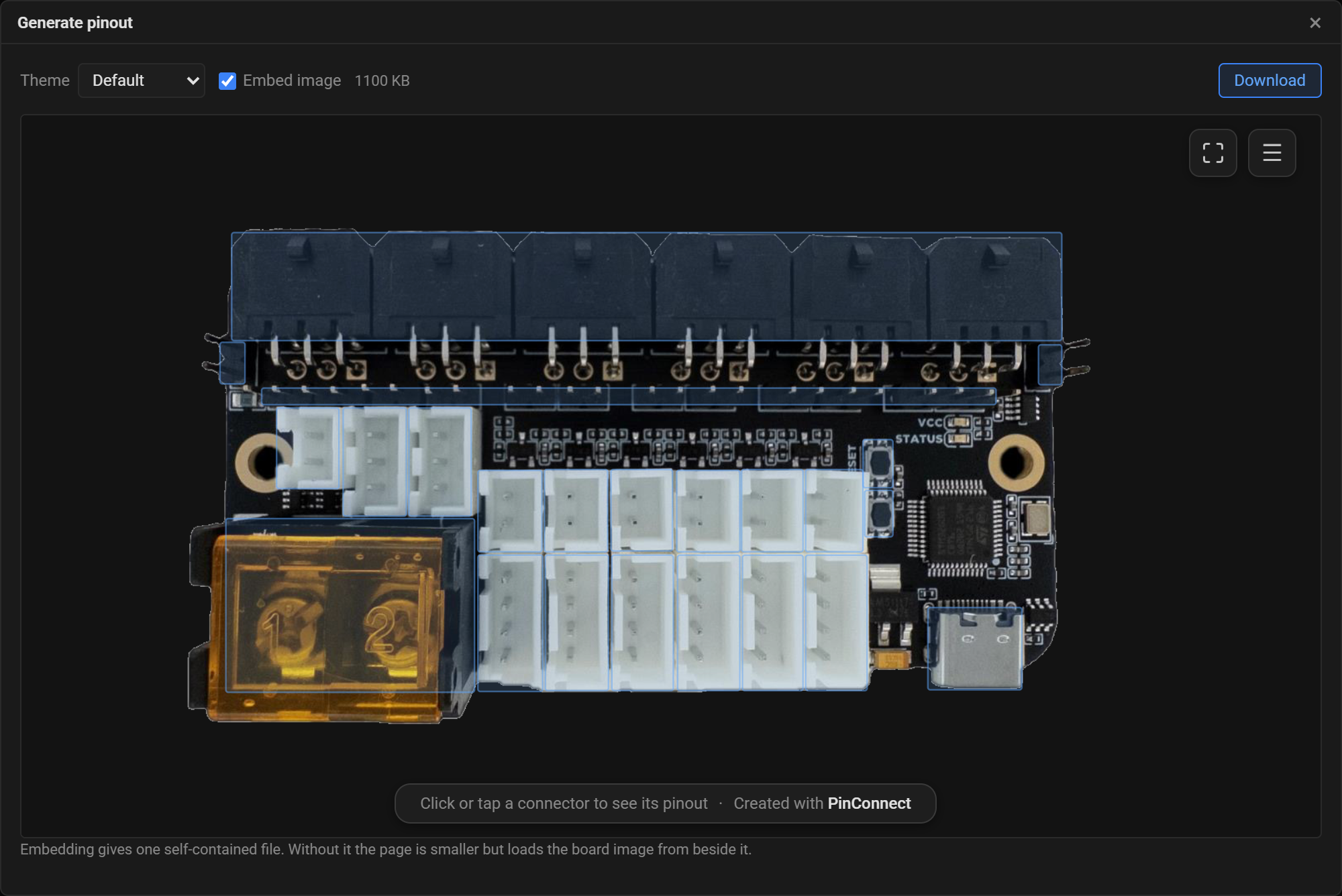
- Theme sets the board's
theme, the same setting as the toolbar's selector, and re-renders, so the page you download always matches the config you save. Undo takes a change back once the dialog is closed. - Embed image writes the board photo into the HTML. On, you get one self-contained file. Off, the file is far smaller but needs the photo beside it. The size beside the toggle is the size of what you are about to download.
- Download saves the page as
<image name>.pinout.html.
If the config cannot be rendered, the dialog shows why and Download is disabled until it can.
8. Save the config
Click Save TOML, and keep the file with your board photo.
The pinout you downloaded is finished and standalone, so this is not for it. It is for the next revision of the board: Open TOML loads the config back in, Open Image brings back the photo, and you carry on from where you left off.
If you close or reload the tab with changes you have not saved, the browser asks you to confirm first. It compares against the last config you saved or opened, so opening one and closing again straight away does not ask.

Keyboard shortcuts
| Shortcut | Action |
|---|---|
Ctrl+Z |
Undo |
Ctrl+Y or Ctrl+Shift+Z |
Redo |
Ctrl+S |
Save TOML |
Ctrl+D |
Duplicate the selected connector |
↑ / ↓ |
Select the previous / next connector while the list has focus |
Home / End |
Select the first / last connector while the list has focus |
Alt+↑ / Alt+↓ |
Move the selected connector up / down while the list has focus, or a jumper setting up / down from anywhere in that setting |
Delete |
Delete the selected connector |
Use Cmd in place of Ctrl and Option in place of Alt on macOS. Undo and Redo are also toolbar buttons. While you are typing in a text field, Undo takes back that typing first, and Redo puts it back. Duplicate and Delete are ignored while you are typing in a text field or using a select menu, and all of these are ignored while a dialog is open.
Troubleshooting
"Renderer unavailable" in the toolbar
The designer downloads its Python runtime from cdn.jsdelivr.net on first load. If that host is blocked by a network policy, an extension or an offline machine, nothing can render: Generate and + Add Connector stay disabled and connectors show as "Unknown type" instead of drawings.
Allow cdn.jsdelivr.net, or use the command line tool, which needs no network at all. Hover the message for the underlying error.
If you serve the designer folder yourself, the same message means its payload, pinconnect.zip, is missing from beside index.html. See serving the designer by hand.
The connector types I need are missing
The designer offers the connector types bundled with PinConnect. It cannot read a type you have written into a board's own connector_dir, because that folder is on your disk and the designer only has the config text.
Such a board still renders, but with the bundled definition of any type whose name it shares, which is not what pinconnect would produce. The Generate dialog says so when it happens. Render those boards with the command line tool, and see connector types for adding a type to the bundled library instead.
The same applies to a theme in a board's own theme_dir.
The board image is missing from the downloaded page
You turned Embed image off, which leaves the page loading the photo from beside it by the path in the config. Either keep the two files together, or download again with the toggle on.