The designer
The designer is where a CAD assembly becomes step-by-step instructions. You import a STEP file, decide what each step shows, moves and highlights, add arrows, labels and a camera, write the text, and press Generate. It also writes a project file as you work, which you save with the models so you can come back to the assembly later.
It runs the real renderer in your browser rather than an imitation of it, so the preview is the file you download, and that file is identical to what the 3dstep command produces from the same project.
Running it
Use the hosted designer at https://3dstep.isiks.tech. Nothing is uploaded: the STEP reader and the renderer both run in your browser, and your files stay on your machine.
To run it yourself, install the tool and run it with no arguments:
That picks a free port, opens a browser, and prints the address. Add --port 8000 to choose the port, or --no-browser to leave the browser alone.
The designer must be served over HTTP. It fetches its runtime at startup, so opening index.html from disk does not work. To serve it with your own web server, see serving the designer by hand.
The interface
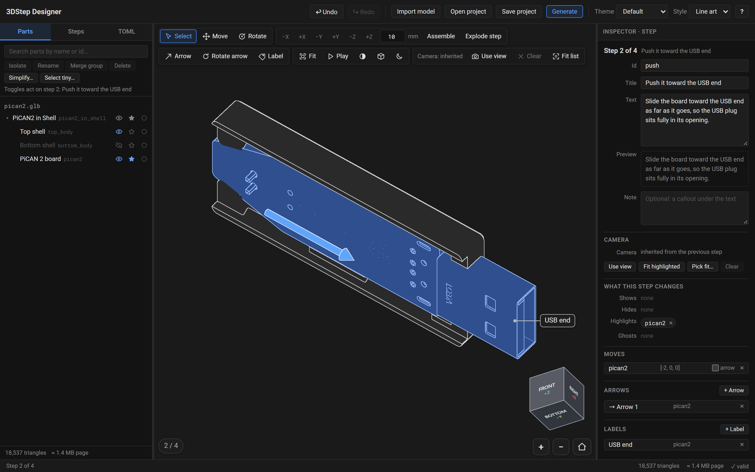
A toolbar across the top, three panels whose dividers you can drag, and a status bar at the bottom:
- Toolbar: Undo, Redo, Import model, Open project, Save project, Generate, the Theme and Style selectors, the renderer's status, and ? for the About box.
- Parts / Steps / TOML (left): the model's parts, the list of steps, and the live, editable project file. The designer remembers which tab you last used.
- Viewport (middle): the model as the page will show it, in the current step, with the tools above it, the view cube in a corner, and the step counter and the zoom and reset-view buttons along the bottom.
- Inspector (right): the current step, or whatever is selected: parts, an arrow or a label.
- Status bar: the step, the selection, the triangle count, the size of the page, and the result of the same checks the
3dstepcommand makes. A count of errors or warnings opens the list; ✓ valid means the command would render the project cleanly.

While the renderer is still starting, the toolbar shows its progress ("Starting renderer…", then "Loading 3DStep…") and Generate is disabled. Everything else works straight away, including importing.
The Theme selector sets the project's theme, and Style its style: line art, white parts with dark edges as in a printed manual, or shaded, in the model's colors. The viewport previews both. The selector lists the bundled themes, then any theme opened with the project, marked "(project)": see a site's own theme. The designer's own chrome keeps its dark colors whichever theme you pick, and the viewport previews the page's dark palette until you switch it with the scheme button in the viewport's toolbar. A theme whose page is transparent, like a docs site's, shows on a white page in the light preview. See Themes.
Below 900 pixels wide the inspector moves under the viewport, and below 700 pixels everything stacks. The designer is a desktop tool: it works on a laptop screen, and a phone is better for checking the generated page than for building one.
Workflow
1. Import a model
Click Import model and choose one or more .step, .stp, .glb or .gltf files, or drop them on the viewport. Each file becomes one model of the project, saved as one GLB file named after it: PiCAN2-in-Shell.step becomes pican2_in_shell.glb. A second import adds a second model beside the first.
For a STEP file, the Import a STEP model dialog asks how to read it:
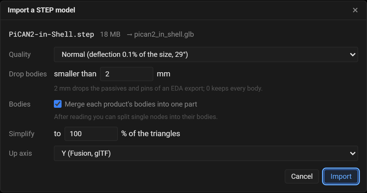
- Quality: how finely curved surfaces become triangles. Fine, Normal or Coarse; each names its deflection, the largest distance between the surface and its triangles as a share of the model's size, and the largest angle between neighboring triangles.
- Drop bodies smaller than: bodies whose bounding box is smaller than this many millimeters across are left out. 2 mm drops the passives and pins of a board exported from an EDA tool; 0 keeps every body. Parts keep the same ids whatever the filter, so you can import again with another value and the steps still find their parts.
- Merge each product's bodies into one part: one part per component of the assembly, which is what you usually move and highlight. Off, every body is a part of its own.
- Simplify: reduce the triangles to this share as the model is added.
- Up axis: the axis that points up in your CAD tool. The first STEP model of a project proposes Y, Fusion's usual axis, or the axis chosen for the last STEP file imported in this session; most other CAD tools export Z-up, and so does a Fusion design made with its Z-up orientation. The first model is never turned: its choice becomes the project's
up, which the Steps tab's Assembly box can change later; see the first model lies on its side. For a model added later it is the file's up axis, starting at the project's: the dialog shows the project's axis, and a file with the other axis up is rotated to it.
Click Import. The reader runs OpenCascade in your browser, off the page's thread, with a progress line and a timer. A small assembly takes seconds and a 40 MB board about a minute. Cancel stops it at once.
Then the dialog shows what the import gives:
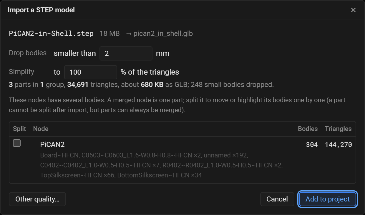
The summary counts the parts, groups and triangles, estimates the model's size, and says how many small bodies the filter dropped. The size filter can still change here, and the summary follows at once; only another quality needs another read, with Other quality…. Simplification runs when you add the model, so the counts are the ones before it.
The table lists every component with several bodies. A merged component is one part; check Split to make each of its bodies a part, to move or highlight them one by one: a bag of screws exported as one component, say. Decide here: a part cannot be split after the import, but parts can always be merged later.
A sub-assembly among the components is such a component too. The STEP reader keeps the assembly's top-level components and flattens everything below them into the component's bodies, so a board exported with its heatsink is one part, its own structure gone, and Split gives one part per body, the heatsink among them, with an EDA board arriving as hundreds of body parts, one per pad and silkscreen stroke. To end with the board as one part and the heatsink as another: check Split, then in the Parts tab select every body of the component but the heatsink's (Shift+click selects a range) and merge them with Merge parts. Or cut the part out of the sub-assembly before the import: 3dstep split takes a component inside a sub-assembly by its path, SM3/SLM HS RC, into a STEP file of its own, placed as in the assembly, which then imports as a model of its own. Or make every part the instructions move on its own a top-level component of the export.
Add to project adds the model. The first model also names an untitled project after its file, sets the project's up axis, and adds a first step. A later model with the other up axis is rotated a quarter turn about X as it is added, so that it stands upright beside the others, and the review says so; its coordinates are then the project's, not its CAD tool's.
A model whose ids another model of the project already uses gets its file name in front of every id, so the page can tell the two apart: import dm1-id-214.glb twice and the second copy, dm1_id_214_2.glb, has dm1_id_214_2_bolt where the first has bolt. The dialog says so before you add it, naming a few of the shared ids and the model that has them. Every id of the model gets the prefix, or none does, and undoing the import takes it back. To convert the same STEP file on a machine later, give 3dstep model.step the same prefix with --id-prefix.
A GLB written by 3DStep is used as it is when it is a project's first model. A later one shows its Up axis, as the file records it, beside the project's, and is rotated to the project's axis when the two differ. A GLB that 3dstep model.step converted always says Z, whatever its CAD file had up: for one from Fusion, choose Y. A GLB from another tool asks for its Unit (millimeters, meters or inches; glTF's own unit is meters) and Up axis (Y, glTF's convention, or Z), and is converted to millimeters and the project's axes.
Large STEP files
The browser's STEP reader can use at most 2 GB of memory, which a STEP file of about 45 MB fills while reading. So the designer reads a STEP file over 32 MB in pieces: the dialog says it is cutting the file into pieces, then reads them one after another ("piece 2 of 4"), each with a fresh reader, and puts the model back together with the same parts, names and colors a whole read gives. The 71.5 MB ToqueCAN 2 assembly takes four pieces and about 100 seconds, and no piece needs more than about 1.2 GB. The pieces are meshed about as finely as the whole file, give or take a few percent of the triangles. If you would rather have the components as separate models of the project, split the assembly with 3dstep split or export several STEP files from your CAD tool, in their assembled positions, and import them one after another. Give each file its own top-level assembly name to keep its ids short: a file with an id that an earlier one already uses gets all of its ids prefixed.
2. Trim the model in the Parts tab
The Parts tab lists every loaded model and its tree of groups and parts. Each row shows the part's name, its id in gray, and three toggles that act on the current step: visible (the eye), highlighted (the star) and ghosted (the dashed circle), which shows the part translucent, for context.
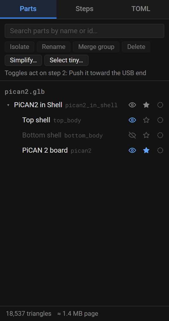
- Search filters the tree by name or id.
- Click a row to select the part, Ctrl+click to add or remove one, Shift+click to select a range. The selection is shared with the viewport and the inspector.
- Isolate shows only the selection in the current step.
- Rename (or
F2, or a double click) changes the part's display name, which the page shows. Its id never changes after the import, so the steps' references stay valid. - Merge group turns the selected group into one part with the group's id. With two or more parts selected, in one model but not necessarily siblings, the button reads Merge parts and merges them into the part you pick in the dialog, the first selected by default: it keeps its id, name and place in the tree, the others leave the model, and a group left without parts goes with them. The steps that named the merged parts name the merged part instead, and Undo brings everything back.
- Delete removes the selection from its model, after a confirmation. The steps stop naming it, and Undo brings it back.
- Simplify… reduces the triangles of the selected parts, or of all of them.
- Select tiny… selects every part whose bounding box is smaller than a size, to delete them together.
The line at the bottom shows the triangle count and the estimated size of the generated page. It turns amber above about 3 MB, the size a page should stay under so it loads quickly on a phone. Deleting what the instructions never show, merging groups or parts and simplifying are the ways down; see Keeping pages small. Merging helps most with a group of many small parts; a merged part with more than 65,535 vertices needs 32-bit indices, so merging one very large group can make the page a little bigger, a 150,000-triangle board from 7.2 to 7.9 MB.
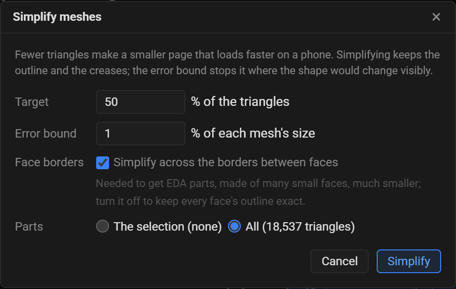
Simplify reduces each part's triangles toward the Target share, as long as the shape stays within the Error bound, a share of each part's size. Simplify across the borders between faces lets it merge triangles across the edges of the CAD faces, which an EDA board needs to get much smaller, since it is made of many small faces; turn it off to keep every face's outline exact.
A model that is not saved as it stands, a new import or one you deleted parts from, merged or simplified, is marked unsaved in the tree until you save.
3. Lay out the steps in the Steps tab
The Steps tab holds the assembly's settings and the list of steps.
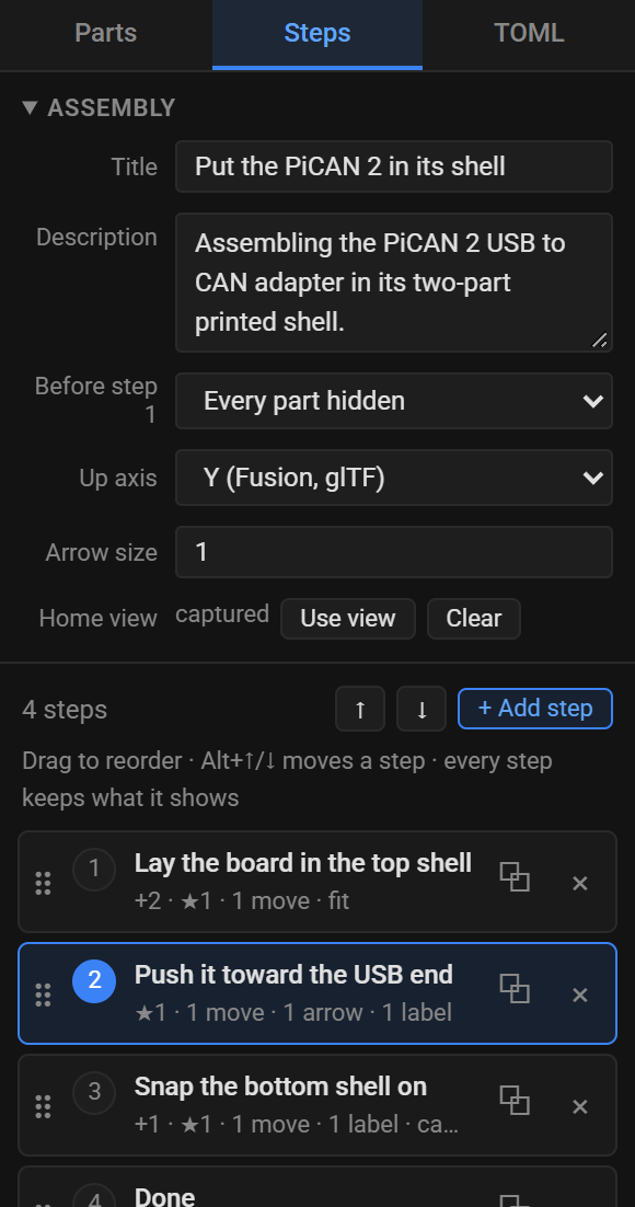
The Assembly box sets the page's Title and Description, what every part is Before step 1 (visible, or hidden when each step adds parts), the Up axis, the Arrow size (a factor on every arrow of the page, arrow_scale in the TOML: arrows are sized from the box around every model, so lower it when a big part makes them too large for the parts the steps are about; see Arrows and labels), and the Home view: Use view makes the current view the page's home view, where step 1 starts, and Clear fits the model instead.
Below it, the list of steps. Each row shows the step's title and a summary of what it changes: +2 shows two parts, −1 hides one, ★1 highlights one and ◌1 ghosts one, then its moves, arrows and labels, and camera or fit when it has a view of its own.
- Click a step to make it current. The viewport, the inspector and the Parts tab's toggles follow.
- + Add step adds a step after the current one, with the same parts visible and nothing moved or highlighted.
- Duplicate copies a step with everything in it.
- Drag a step, or use the ↑ and ↓ buttons or
Alt+↑/Alt+↓, to reorder. - × deletes a step.
Every step keeps what it shows: reordering or deleting steps, and showing or hiding parts in one, rewrites the project so that every other step still displays the same parts. Showing a part makes it visible in the current step only; Shift+click its eye to show it from the current step on.
4. Work in the viewport
The viewport shows the current step as the page will, with the tools in a toolbar above it.
- Look around: drag to rotate, right-drag to pan, scroll to zoom, double-click to center the view on a point. The view cube in the corner flies the view around: click a face to look from that side, an edge to look from between two sides, a corner to look from three at once. Its faces are named as in Fusion: with Z up, the front is −Y; with Y up, +Z.
- Select: click a part to select it, Shift+click or Ctrl+click to add or remove one, Alt+click to select its group, click empty space to clear. Clicking an arrow or a label selects it.
The tools, in groups:
| Tool | Key | What it does |
|---|---|---|
| Select | Selects parts, arrows and labels. | |
| Move | G |
Drag the gizmo's arrows or planes to move the selection. It moves in 1 mm steps; hold Alt to move freely. |
| Rotate | R |
Drag the gizmo's rings to turn the selection about its center, in 15° steps; hold Alt to turn freely. |
| −X +X −Y +Y −Z +Z | Move the selection along an axis by the distance in the field beside them, in millimeters. Presses add up. | |
| Assemble | Put the selection back in its assembled place, or with nothing selected every part of the step. | |
| Explode step | Stack the parts the step highlights along the up axis, above the rest and the distance apart, so none overlap. | |
| Arrow | A |
Click a point on a part for the tail, then a second point for the head. Hold Shift for the head to stay on the line straight out of the first surface. |
| Rotate arrow | Shift+A |
Click a surface: an arrow turns around the line straight out of it, sized to the part. |
| Label | L |
Click a point on a part, then type the label's text in the inspector. |
| Fit | F |
Fit the view to the selection, or to everything shown. |
| Play | Play the step's moves, as the page's Play button does. Again: back to the start. | |
| Style, projection, scheme | Switch the project between line art and shaded; the view between orthographic and perspective (Use view stores it in the step); and the preview between the page's light and dark palette. | |
| Use view | Use the current view as the step's camera. | |
| Clear | Clear the step's camera: it uses the previous step's again. | |
| Fit list | Make the step's camera frame the selection, or with nothing selected the parts the step highlights, from the previous step's direction. |
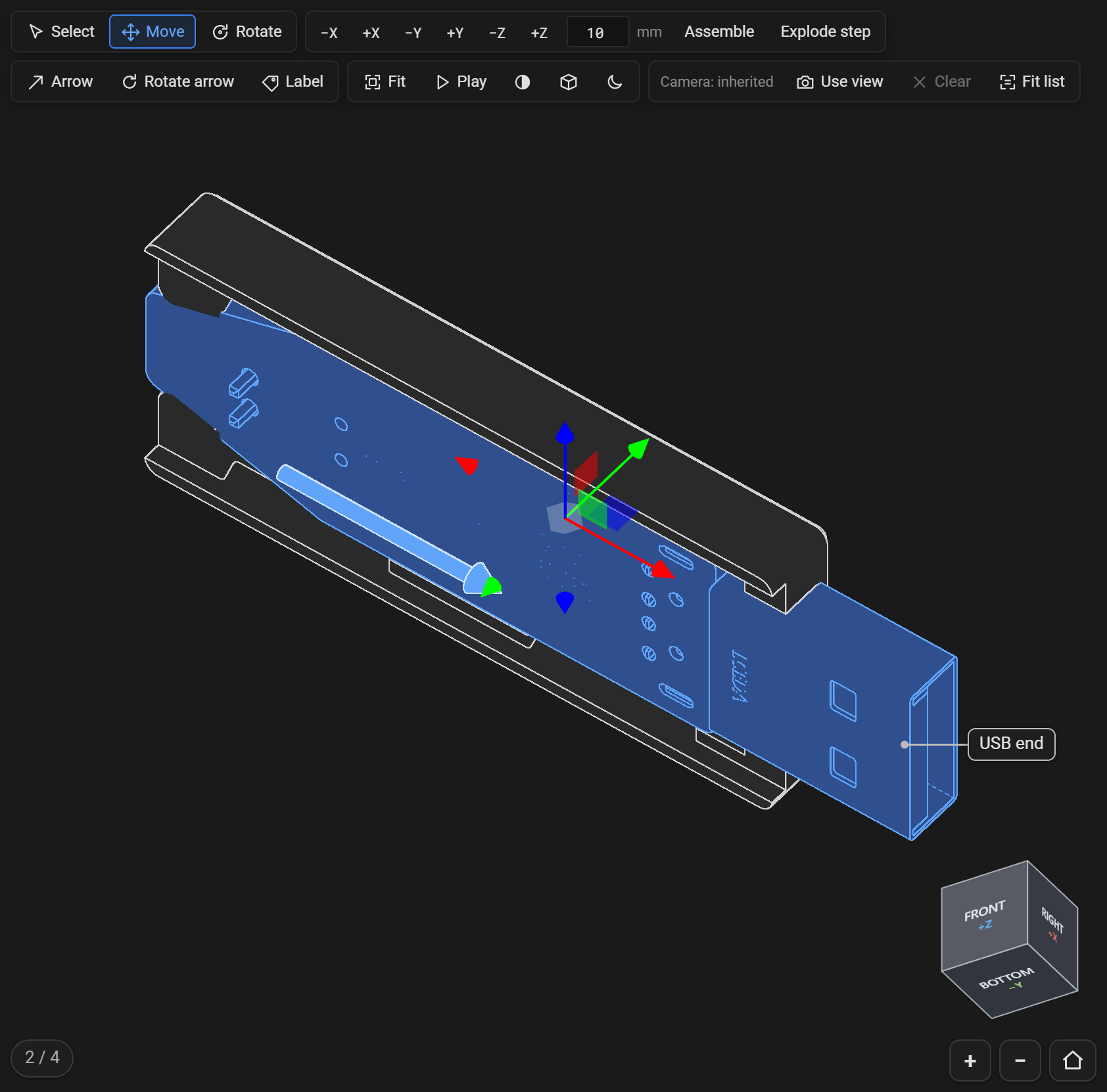
A move places parts for the current step only, relative to their assembled place. Move a part out with the gizmo or the axis buttons, and the page shows it there, with an arrow back to where it goes, and plays it into place when the reader presses Play or goes on to the next step. Moving several parts at once moves them as one rigid body. A drag is one undo step, and Esc during a drag puts the parts back.
Arrows and labels placed with the tools are attached to the part you click: their points are stored in that part's frame, so they travel with it while it moves. While you place an arrow, a preview follows the pointer and a line at the bottom of the viewport says what the next click does:
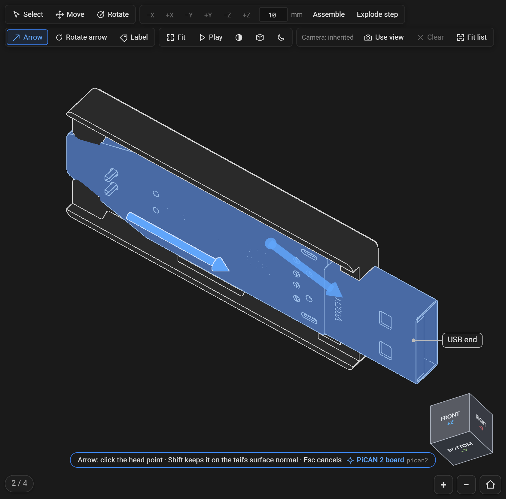
A click lands on the first surface under the pointer, so where one part lies in front of another, it takes the front one. While the Arrow, Rotate arrow or Label tool is active, or the inspector's Pick or Pick fit… waits for a click, the part a click would land on is tinted with a softer version of the selection color, and its name and id follow the prompt.
Esc cancels a tool's pending click, then goes back to Select; with Select active it clears the selection.
5. Edit in the inspector
The inspector edits whatever is selected. With nothing selected, it edits the current step:
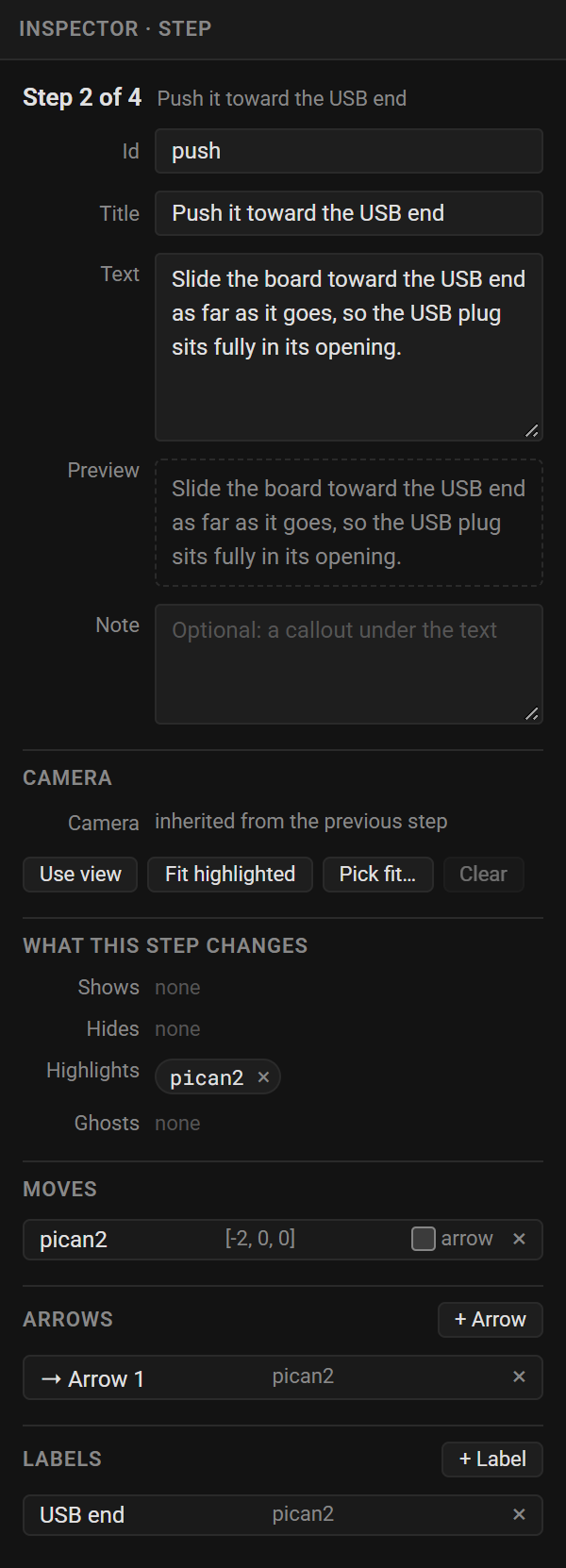
- Id names the step in links (
?step=push). Leave it empty forstep-2and so on. - Title, Text and Note: the instruction. A blank line in the text starts a paragraph, and
**bold**,`code`and[links](https://example.com)work; the Preview shows the result. The note appears as a callout under the text. - Camera says where the step's view comes from, the previous step's, its own, or a fit to parts, with Use view, Fit highlighted (frame what the step highlights), Pick fit… (click the parts to frame in the viewport,
Escto finish) and Clear. - What this step changes lists the ids it shows, hides, highlights and ghosts. Click one to select it, or × to take it out of the list.
- Moves, Arrows and Labels list the step's own. Click one to select it. A move's arrow checkbox draws the arrow from the part to its assembled place, and its × puts the parts back. + Arrow and + Label add one to edit by hand.
With parts selected, it shows their Id (fixed), their name in the CAD file, a display Name, and a Color that overrides the model's in the shaded style; then the current step's Visible, Highlight and Ghost checkboxes, the move's Offset in millimeters and Rotate in degrees about each axis, the Auto arrow checkbox, and buttons for the Move and Rotate tools, Fit view, Isolate and Remove from step.
With an arrow selected, it edits its Kind (straight, or rotate around an axis), its two points (From and To, or Center and Axis to), the rotate arrow's Turns and Radius, a Color, a Label at its tail and the part it is Attached to. A label has its Text, Anchor, Side and attachment. Pick beside a point takes it from a click in the viewport. Unchecking Attached converts the points to model coordinates, and checking it again converts them back, so nothing moves on screen. Step returns to the step.
A rotate arrow placed with the tool turns clockwise as you look at the surface you clicked, the way a screw goes in: its Axis to point is inside the part. To show one coming out, make its Turns negative; turns explains the rule.
6. Edit the TOML directly (optional)
The TOML tab holds the project file, live. The two directions stay in step: type there and the viewport updates, change something with the panels and the text updates. It is useful for bulk edits, or for pasting in camera numbers.
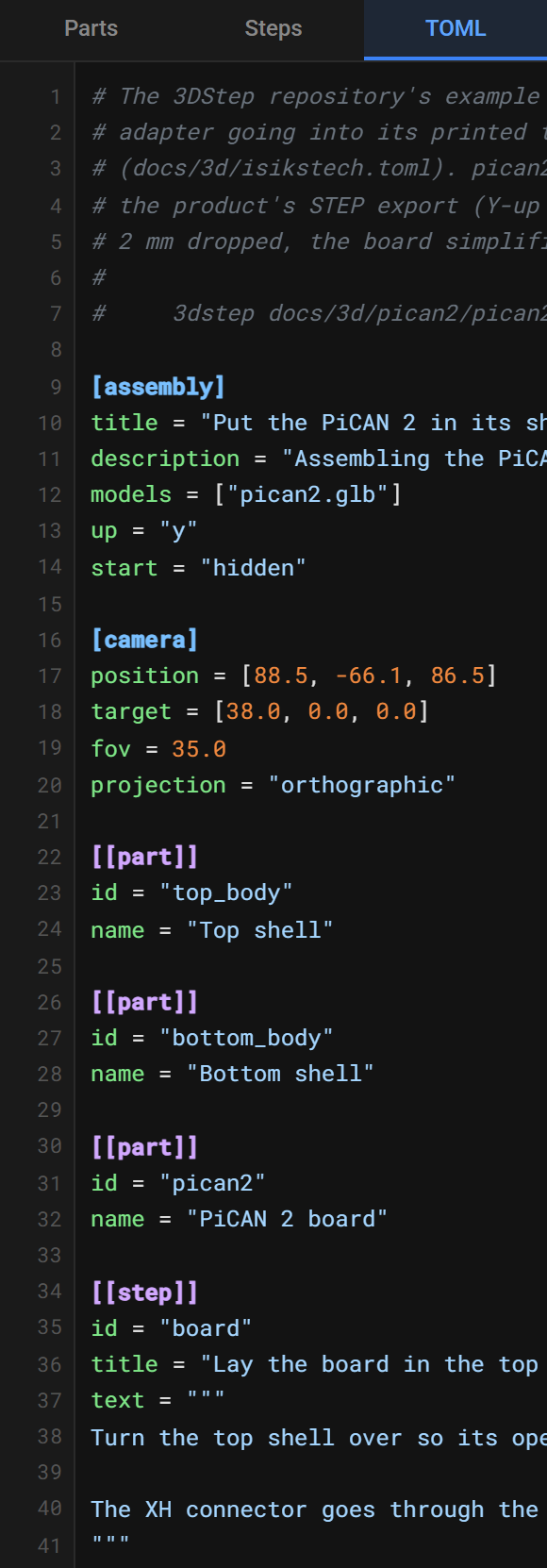
Edits made with the panels rewrite only the values that change, so your comments and layout stay as written. Text that does not parse keeps its place with the error, and blocks edits from the panels until you fix it. Naming a model file the designer has not loaded shows a banner with a button to open it.
7. Generate the page
Click Generate. The dialog renders the page with the same code as the 3dstep command and shows the real page, sized by its own height report the way a docs site embeds it.
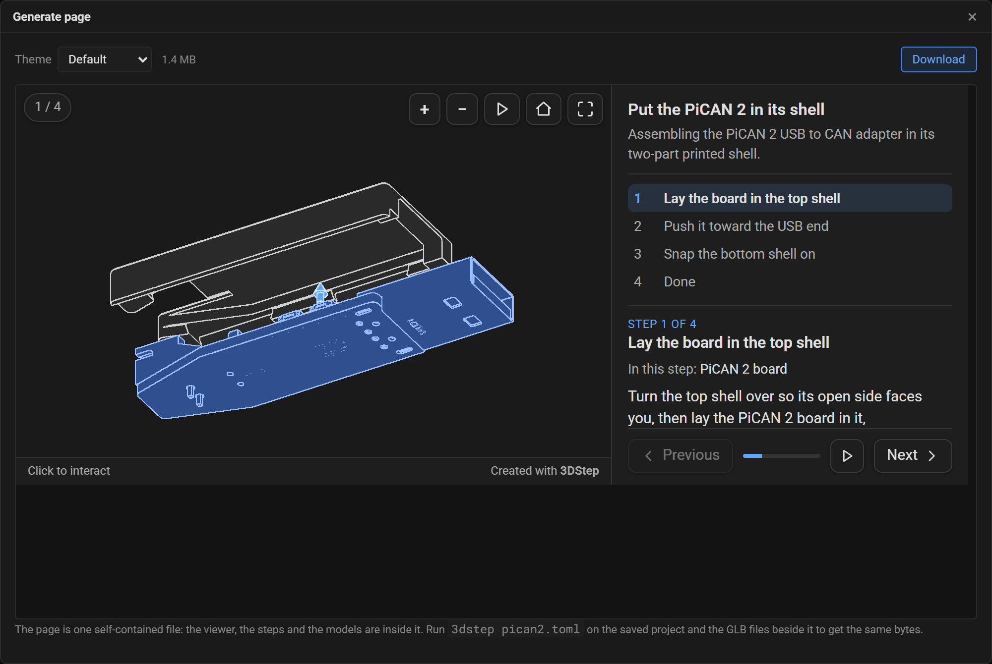
- Theme sets the project's
theme, the same setting as the toolbar's selector, and renders again, so the page you download matches the project you save. It lists the bundled themes and those opened with the project, and starts on the project's own. - The size beside it is the size of the page you are about to download.
- Download saves the page as
<project name>.3dstep.html.
Problems the page renders with anyway are listed above the preview. If the project cannot be rendered, the dialog shows why and Download is disabled until it can. A project whose theme is neither bundled nor opened is one of those: the dialog says which file to open, and its Open <theme>.toml button opens it and renders again.
8. Save and open projects
Click Save project (Ctrl+S). It saves the project file, <name>.toml, then every model marked unsaved, as <model>.glb. The name is the opened project file's, else the title in the Steps tab made into a file name the way ids are (Mount the PCB saves as mount_the_pcb.toml), else the first model's (pican2_in_shell.toml beside pican2_in_shell.glb); where the browser lets you choose, the dialog proposes it, and the project keeps the name you pick for the next save. Where the browser lets a page choose where files go, you pick the folder for the TOML and each model is suggested beside it; elsewhere they download. Keep them in one folder: the project finds its models by file name, and a banner reminds you which files belong together.
Open project takes the TOML and its GLB files together, chosen at once or dropped on the viewport together. A project whose models are not all loaded shows a banner naming them, with a button to open each of the first three.
Each GLB file is matched to the name the project gives it, in any case: DM1-ID-214.glb opens as dm1-id-214.glb when that is the project's name for it, as the 3dstep command finds it on Windows and macOS. The project keeps its own spelling, and the status bar names the file opened under another one; see a file opened as another name.
If you close or reload the tab with changes you have not saved, the browser asks you to confirm first.
A site's own theme
A project can read its theme from a folder of its own, as the examples on this site do: a docs site keeps its theme beside its projects and points theme_dir at it. The designer cannot read that folder, so open the theme's .toml together with the project, its GLB files and any font file the theme's [font] names, or drop them all on the viewport. A .toml with [theme] or [colors] tables and no [assembly] is taken for a theme, not a project.
The designer then finds the theme where the 3dstep command would: the Theme selector lists it as <name> (project), the viewport previews its colors in both schemes, and Generate gives the command line's page, byte for byte. An opened theme takes the place of a bundled theme of the same name, as a file in theme_dir does for the command line.
A project whose theme is neither bundled nor opened previews with the default look, and a banner names the file, with an Open <theme>.toml button. A theme file opened on its own, with that button, Open project or a drop, joins the project on screen. The designer only reads theme files, never changes or saves them, and they belong to the project they were opened with: opening another project drops them, and undoing that Open brings them back.
Keyboard shortcuts
| Shortcut | Action |
|---|---|
Ctrl+Z |
Undo |
Ctrl+Y or Ctrl+Shift+Z |
Redo |
Ctrl+S |
Save project |
Ctrl+D |
Duplicate the current step |
← / → |
Previous / next step |
G, R |
Move tool, Rotate tool |
A, Shift+A, L |
Arrow tool, Rotate arrow tool, Label tool |
F |
Fit the view to the selection, or to everything shown |
Delete or Backspace |
Take the selected parts out of the current step (its lists and moves), or delete the selected arrow or label |
Esc |
Cancel the tool's pending click, then back to Select; with Select, clear the selection. In an inspector field, leave the field |
Alt while dragging the gizmo |
Move or turn freely instead of in 1 mm and 15° steps |
↑ / ↓, Home / End |
In the Parts tree or the step list: select the previous / next, first / last row |
Alt+↑ / Alt+↓ |
In the step list: move the step up / down |
Delete |
In the step list: delete the step |
→ / ← |
In the Parts tree: open / close a group |
Space |
In the Parts tree: show or hide the part in the current step |
F2 |
In the Parts tree: rename the part |
Use Cmd in place of Ctrl and Option in place of Alt on macOS. The tool keys and the step keys are ignored while you are typing in a field, and all of these are ignored while a dialog is open.
Troubleshooting
"Renderer unavailable" in the toolbar
The designer downloads its Python runtime from cdn.jsdelivr.net on first load. If that host is blocked by a network policy, an extension or an offline machine, the designer cannot render: Generate stays disabled, and the status bar cannot check the project. Importing, editing and saving still work.
Allow cdn.jsdelivr.net, or render the saved project with the command line tool, which needs no network at all. Hover the message for the underlying error.
If you serve the designer folder yourself, the same message means its payload, threedstep.zip, is missing from beside index.html. See serving the designer by hand.
The import runs out of memory
The designer reads a big STEP file in pieces (see Large STEP files), and a piece that runs out of memory, in a browser that allows less than 2 GB, has the file cut again, finer, which the dialog says. What can still run out is a single body too big for the reader on its own, "Out of memory while reading <file>: one body of "<product>" alone fills the 2 GB the STEP reader can use", or a file that runs out even in small pieces, whose message suggests the coarse quality, which is worth one try. A file that cannot be cut at all, one solid with nothing else, gets "Out of memory while reading <file>" followed by what to try. The designer keeps working either way. Convert such a file on a machine with 3dstep model.step, which has no such limit, and import the GLB it writes, or split the body in your CAD tool.
My theme is missing
The designer has the themes bundled with 3DStep and the theme files opened with the project. A theme kept in a project's own theme_dir, like a docs site's, is on your disk, where the designer cannot look: until you open its file, the project previews with the default look, a banner offers to open the file, and Generate says which file it needs. The status bar reports the theme as an error when it is meant to be in ./themes, the default theme_dir, where a missing file is most likely a typo, and as a warning with another folder, where the command line may find it. Open the theme's .toml with the banner's button, Open project or a drop, and the designer previews and generates with it; see a site's own theme.
A theme whose [font] uses source = "bundled" needs its font file as well: open it together with the theme. Until then the status bar warns that the font file is missing, naming it as the theme does, and Generate stops with the same message.
Picking another theme in the Theme selector or the Generate dialog renders with that one, but it sets the project's theme too: undo it before you save, or the project loses its own theme's name.
The status bar says a file was opened as another name
Open matches a GLB file to the name the project gives it in any case, so dm1-id-214.glb opens for a project naming DM1-ID-214.glb. The project keeps its own spelling, and the status bar says "dm1-id-214.glb opened as DM1-ID-214.glb"; hover it for the details. The 3dstep command finds that file under the project's spelling on Windows and macOS, whose file systems ignore case, but not on Linux, which is what most CI runners use: rename the file to match. A model or theme opened with a banner's button under another name altogether is named the same way.
The status bar says two models share an id
The page cannot tell apart the parts of two models that share an id. The designer prevents it when you import a model, by prefixing its ids, but opening a project renames nothing: the warning means the project's GLB files already shared ids when you opened them, or a GLB was converted again with 3dstep model.step without the --id-prefix the designer gave it. Convert one of the two models again with --id-prefix and add the same prefix to the ids the project names from it, or import it again in the designer, which prefixes the new copy's ids, and point the steps at those.
The first model lies on its side
The project's up axis is the one chosen in its first model's import dialog, which proposes Y, Fusion's usual axis, or the axis chosen for the last STEP file imported in the session, whatever the file has. The first model is never turned, so a wrong choice moves nothing, but the view cube's Top then looks at the model from the side, the home view, which looks from the front, the right and above, is taken from the wrong side, and Explode step stacks the parts sideways. Change the Up axis in the Steps tab's Assembly box: the model stays where it is, and the view cube, the views and the exploding follow. Do it before adding more models: a model added later with the other axis up is rotated to the project's axis, so a wrong project axis turns it the wrong way.
A model added later lies on its side
The project's up axis comes from its first model, and a model added later is rotated to it from the up axis its import dialog showed. A model lies on its side when that axis was wrong for it: most often a GLB converted by 3dstep model.step, which says Z even when its CAD file is Y-up, as Fusion's usually are. Undo the import and import it again with the file's real up axis. Opening a project rotates nothing. If the project's first model lies on its side, see the first model lies on its side instead.