Getting Started
This guide takes you from a photo of your board to a finished interactive pinout. It happens entirely in your browser and takes about five minutes.
What you need
- A top-down image of your board, in any format a browser can display.
- A browser. Nothing else: the designer downloads what it needs and runs the generator itself, so there is no install step.
The first load fetches a Python runtime of roughly 10 MB, which takes a few seconds and is then cached. The toolbar tells you when it is ready.
Step 1: Open the designer
Go to https://pinconnect.isiks.tech. The generator runs in your browser, so your photo and your config never leave it.
If you prefer to run it yourself, install the tool and run it with no arguments instead:
That builds what the designer needs, starts a local server, and opens a browser. See Command line and CI for the details.
Step 2: Load your board photo
Click Open Image and choose your photo. It sets the coordinate space for everything you place on top of it.
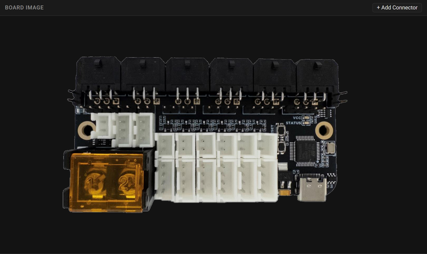
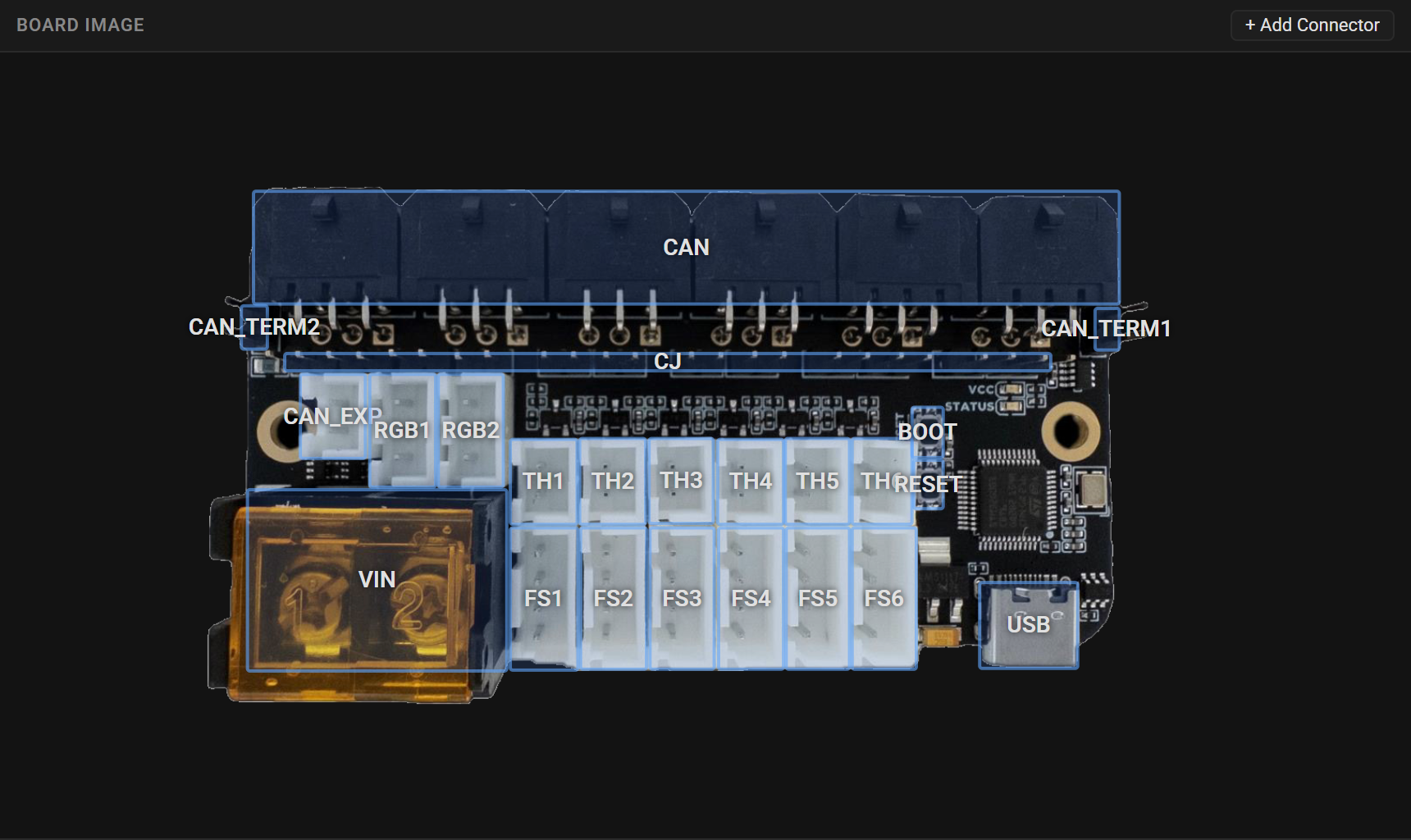
Step 3: Draw a box over each connector
The Connectors tab is open on your first visit. Click + Add Connector in the list or above the board, then drag a box over a connector in the photo. Releasing the drag opens a dialog where you give the connector an ID, an optional name, and a type from the built-in library.
Draw mode switches itself off after each connector, so click the button again for the next one.
Step 4: Label the pins
Select a connector in the Connectors list or on the board to edit it. Set its type, orientation and description, then name each pin and give it the color of the wire that goes there.
Pin order in the list is the physical pin order in the output, so drag the handles until they match the board.
You can also drag the handles in the Connectors list to set the order of connectors in the finished pinout. Use a row's Duplicate button to copy a connector with its pins, then move its box to the next matching connector on the board.
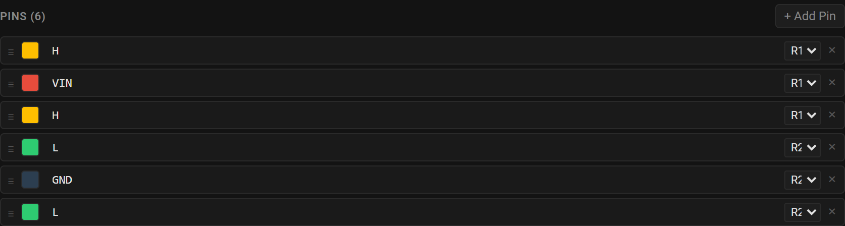
The designer covers every field in detail.
Step 5: Generate
Click Generate. The dialog renders your pinout and shows it exactly as it will look.
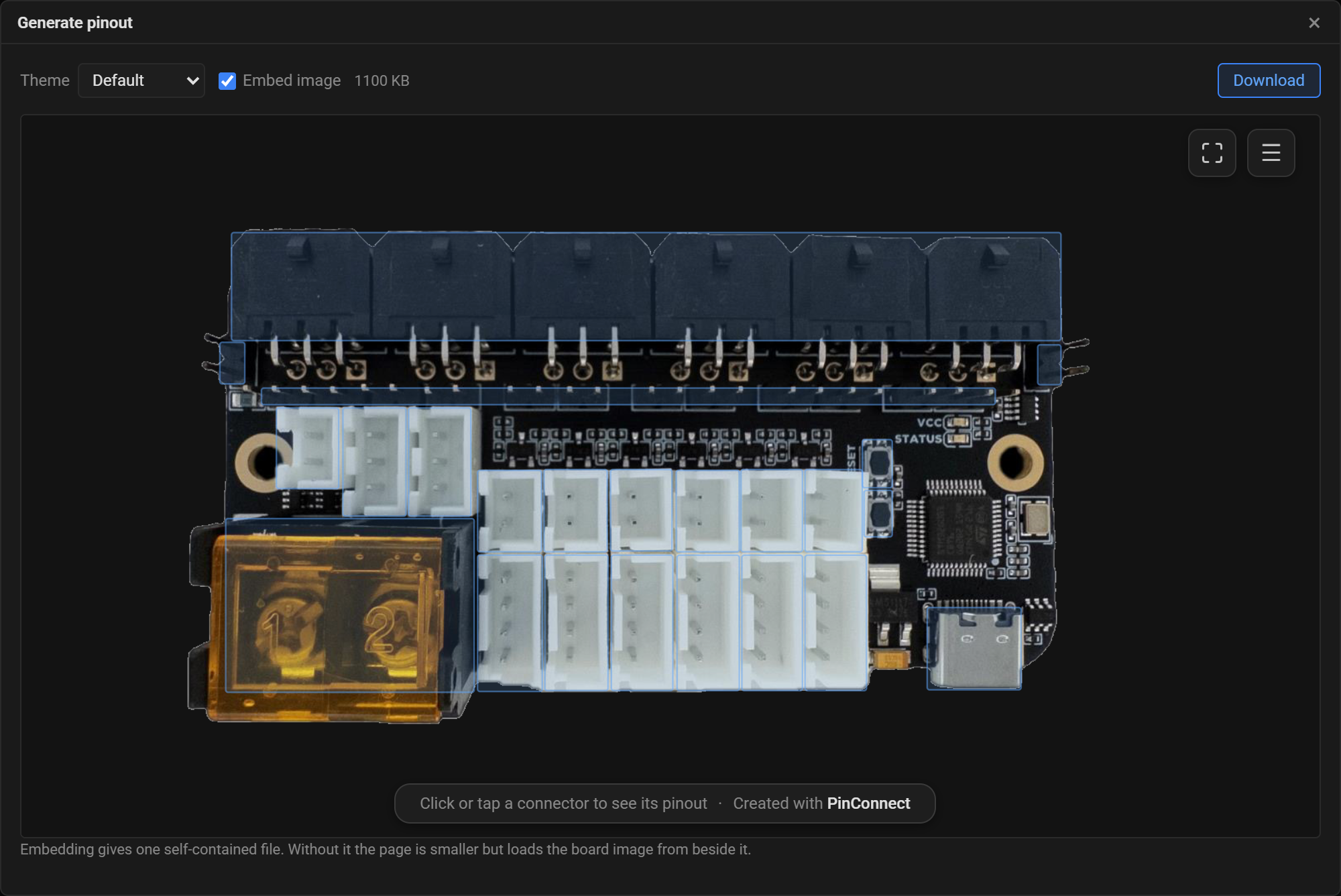
Two controls are worth knowing:
- Theme changes the colors, fonts and layout of the finished page. Six are built in. Switch between them to see the effect immediately, and read Themes to write your own.
- Embed image decides whether the board photo is written into the HTML. Leave it on and you get one self-contained file that works anywhere. Turn it off and the file is much smaller, but the photo has to sit beside it.
Click Download to save the page. Open it in a browser and you have a page like this one, live here. Hover a connector on the board for its pinout, or open the connector list to browse every connector at once:
Step 6: Save the config too
Click Save TOML to keep the config the designer has been writing as you work. You can inspect or edit it in the TOML tab; saving works from either tab.
You don't need it for the pinout you just downloaded, but it makes editing pinouts much easier: load it back with Open TOML, adjust, and generate again.
Where to go next
- The designer: every panel and field, plus what to do when something looks wrong.
- Concepts: what the config actually describes, and how connector types and themes are resolved.
- Command line and CI: regenerate pinouts from the command line, or from CI.
- Embedding with md-iframe: put the pinout into an MkDocs or Zensical page.